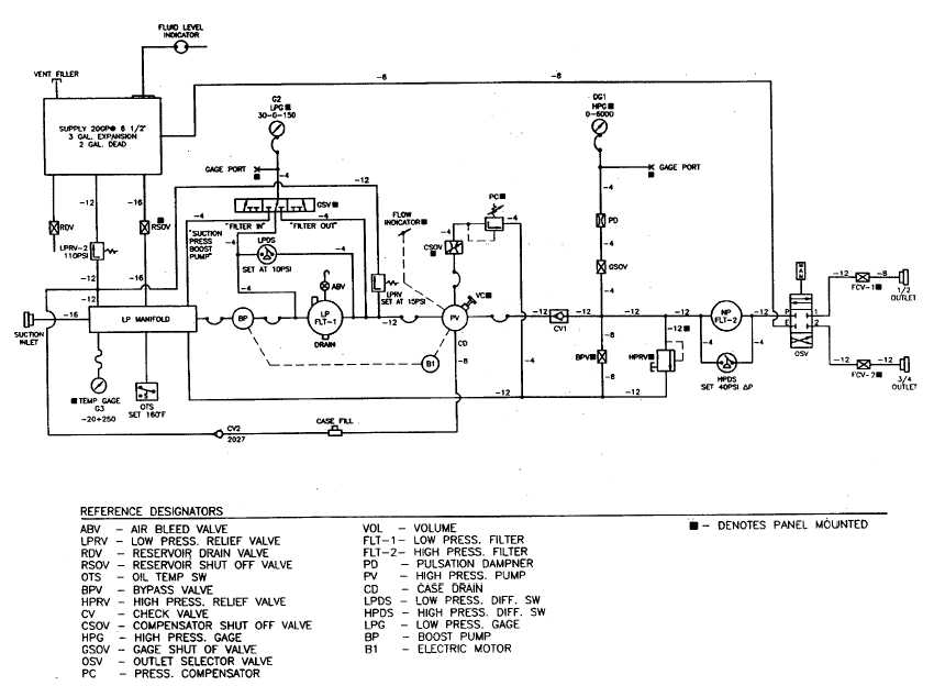
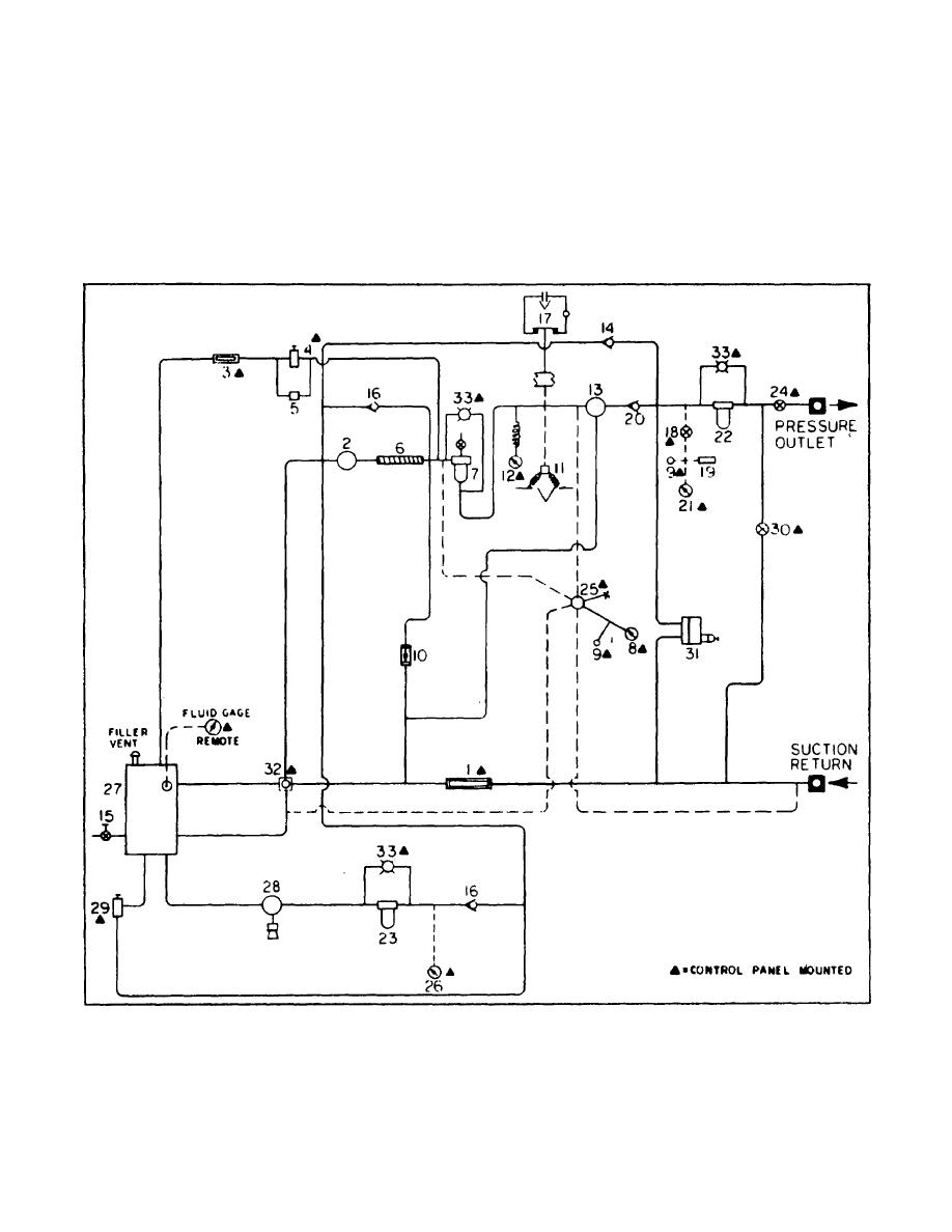
Hydraulic Test Stand Schematic

Aircraft systems uses this test stand for military aircraft units.
Hydraulic test stand schematic. 0 25 000 psi air pressure. Pneumatic hydraulic supply pp200sp and three independent test stands fully automatic test runs based on component maintenance manuals cmms test procedures 3 self sufficient test stands. Operator s controls and instruments are located at the right rear side of the. Note left and right sides are determined standing at the towbar and facing the test stand.
The word hydraulic is derived from two greek words. Speed 750 5 000 rpm. 0 3 000 psi 15 gpm static test pressure. Hydraulic therefore is an adjective implying that the word it modifies is in some major way concerned with liquids.
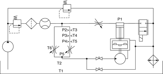
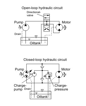
To analyze the capabilities of the hydraulic test bench it was necessary to research hydraulic circuit diagrams and construct a circuit for each valve to be tested. Examples can be found in the everyday usage of hydraulic in connection with familiar items such. Hydraulic schematic symbol flashcards by john rosz. Eha can design a system to meet your every need.
They are designed to be flexible to test valves pumps motors and other components. Once the hydraulic circuits were constructed the system was run at two different system pressures of 200psia and 400psia. Test stand for testing hydraulic devices. 40 hp up to one hour.
Test stand for valves and high flow components pp200vhf test stand for air cycle machines pp200acm test stand for air turbine starters. 11kip 50kn mts 812 21 bench top fatigue frame 12624 01. General purpose test stands general purpose test stands are designed to test any hydraulic component or system. 50 hp intermittent 3 minutes.
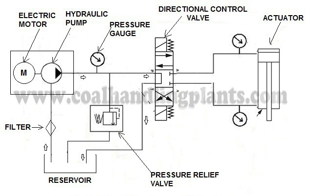
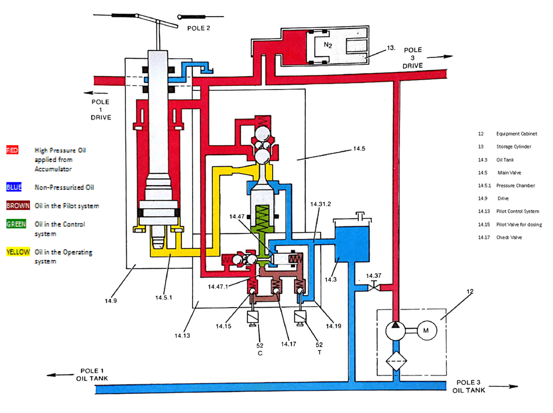
This invention relates generally to a hydraulic test bench and more particularly to a test bench for testing hydraulic pumps and motors having horsepower ratings several times that of the primary power source of the test bench. It shows the technician how it works what each com ponent should be doing and where the oil should be going so that he can diagnose and repair the sys tem. The dia gram shows how the components will interact. Below are some of this test stand s capabilities.
1 is a schematic illustration of an embodiment of the. Introduction to hydraulic schematics. Used hydraulic test bench 50 hp 3 60 also has a 200 gallon reservoir tank and stand. Click to request price.
Learners quiz themselves using electronic flashcards. The pump is driven by a 20 horsepower 220 440 volt 60 hertz 3 phase motor. Hydro meaning liquid or water and aulos meaning pipe or tubing. This interactive object is designed to help learners memorize schematic symbols used in hydraulic diagrams.
Accurate diagrams of hydraulic circuits are essen tial to the technician who must repair it.


